ICSE Revision Notes for Electrical Power and Household Circuits Class 10 Physics

Chapter Name | Electrical Power and Household Circuits |
Topics Covered |
|
Related Study |
Electrical Power and Household Circuits
Measurement of Electrical Energy
- Let a current I flow through a conductor of resistance R for time t when a source of potential difference V is applied across its ends.

- One joule of work is done when one coulomb of electric charge flows from higher potential to lower potential through a potential difference of one volt.
- Hence, when Q coulomb of electric charge flows through a potential difference of V volt, the work done W is given by
W = QV
But we know that Q = It. Thus, we have
W = VIt joule - This work W measures the electrical energy supplied by the external source in providing I ampere current for t seconds in the conductor under a potential difference of V volt.

Other expressions for electrical energy by using Ohm's law
W = Vlt = I2Rt
⇒ W = (V/R)2 .Rt = V2t/R
- The SI unit of electrical energy is joule (J).
Electrical Power
- Power is the rate of doing work, i.e. it is the work done (or energy consumed) in 1 s. In an electrical circuit, we define power as the rate at which electrical energy is supplied by the source. .
Power = (Energy supplied)/Time
= W/t
Power = Vlt/t = Vl
Power = V2/R
OR Power = (lR)2/R = l2R
Units of Electrical Power
- The SI unit of power is watt (W) or J s−1.
- One watt is the power consumed when a current of 1 ampere flows through a circuit with a potential difference of 1 volt.
- The bigger units of power are
▪ 1 kilowatt (1 kW) = 1000 W
▪ 1 megawatt (1 MW) = 106 W
▪ 1 horsepower (1 hp) = 746 W
Commercial Unit of Energy
- In practice, the unit used for energy is watt hour and its bigger form is kilowatt hour.
- One watt hour is the electrical energy consumed when an appliance of one watt power is used for one hour.
- One kilowatt hour is the energy consumed by an electrical appliance of power 1 kW when it is used for one hour. It is termed unit.
1 kW h = 3.6 ×10⁶ J - The electricity bill which one pays is the bill for consuming energy which is needed to keep the electrons flowing in the circuit.
Power Rating of Common Electrical Appliances
- An electrical appliance such as an electric bulb, geyser or heater is rated with power and voltage.
- The following two quantities can be calculated from this rating:
- Resistance of filament of the bulb when it is glowing
- Safe limit of current which can flow through the bulb while in use
- Resistance of the filament of the bulb as
R = V2/P
= (Voltage rating on appliances)2/(Power rating on the appliances) - The safe limit of the current through the filament of the bulb is P
l = P/V
= (Power rating on appliance)/(Voltage rating on the appliance)
Household Consumption of Electrical Energy
- The electrical energy consumed by an appliance in a certain time can be calculated in kWh by the following relation:
Energy in kWh = Power (in kW) × time (in h)
- The cost of electricity will then be the product of energy consumed in kWh with the rate per kWh.

Heating Effect of Electric Current
When an electric current is passed through a metallic wire, the wire gets heated up. This shows that electrical energy is converted into heat energy. The amount of heat produced in the wire depends on three factors:
- Amount of current passing through the wire: H ∝ l2
- Resistance of wire: H ∝ R
- Time for which the current is passed in the wire: H ∝ t
Thus, we have the heat H as
H ∝ l2Rt
The above equation is also known as Joule's law of heating.
Transmission of Power from the Generating Station to Consumer
- At the generating station, the electric power is generated at 11,000 volt because voltages higher than this cause insulation difficulties, while voltages lower than this involve high current. ∙ The voltage is an alternating voltage of frequency 50 Hz.
- For a given electric power, the current becomes low at a high voltage, and therefore, the loss of energy due to heating (H = I2Rt) in the line wires becomes less.
- Thus, the alternating voltage generated is first stepped up from 11 kV to 132 kV at the generating station (or called the grid sub-station) using a step up transformer. It is then transmitted to the main sub-station.
- The transmission of electricity from the generating station is shown in the figure below.


Power Distribution in a House
- The electric connections for the supply of electric power from the city sub-station to the distribution box of a house through a meter, main fuse and main switch are shown below.

- The neutral and earth wires are connected together at the local sub-station so that they are at the same potential.
- The live wire is also called the phase wire. The live wire carries current from the source to the distribution board, while the neutral wire is for the return path of the current.
- Before the electric line is connected to the meter in a house, a fuse of high rating is connected in the live wire at the pole or just before the meter. This fuse is called the company fuse or pole fuse.
- The cable is then connected to a kWh meter. The kWh meter is usually mounted on the front or outside wall of the house.
- The main fuse is connected in the live wire, while the main switch is connected in the live and neutral wires. The main switch is a double pole switch.
- The covering is earthed.
- The earth wire from the meter is locally earthed.
House Wiring
- In a house, the wiring is commonly done by either of the following two systems:
1. Tree system
2. Ring system
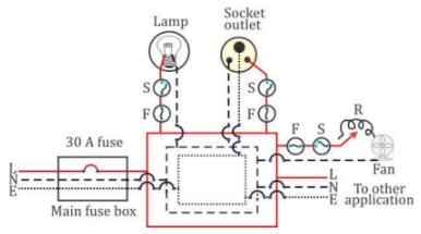
The Tree System
- In this system of wiring, different branch lines (or distribution circuits) are taken from the distribution board to the different parts of the house. These distribution circuits look like the different branches of a tree.
- The figure below shows the fuses F, F, F connected in the live wire at the distribution board in each distribution circuit leading to the different rooms.

- The number of distribution circuits from the distribution board depends on the total power consumption in different portions of the house.
- The total load of all the circuits together must not exceed the specified value for which the connection is taken from the company, otherwise the pole or main fuse will burn.
- The different distribution circuits through their live wires are connected in parallel at the distribution board so that if there is a short circuit in one distribution circuit, its fuse will blow off without affecting the electric supply in the other circuits.
Disadvantages of the Tree System
∙The tree system has the following disadvantages:
- It requires plugs and sockets of different sizes for different current-carrying capacities.
- When the fuse in one distribution line blows, it disconnects all the appliances from the supply connected in that distribution circuit.
- This type of wiring is expensive.
- If a new appliance requiring higher current, say 15 A, is to be installed in a distribution circuit which is initially for 5 A rating, then it is necessary to put the new line wires from the appliance up to the distribution box. This makes it expensive and inconvenient.
The Ring System
The ring system of electric wiring is shown in the figure below.
- This system has a ring circuit. The wires starting from the main fuse box run around all the main rooms of the house and then come back to the fuse box again forming a ring.
- One terminal of the appliance is connected to the live wire through a separate fuse and a separate switch and the other terminal to the neutral wire. The earth terminal or metal covering of the appliance is connected to the earth wire.
Advantages of the ring system
The ring system has the following advantages:
- In the ring system, the current can travel to an individual appliance through two separate paths. Thus, the connection for each appliance effectively comes through a thick wire. Therefore, the wire required for the main ring is of a lower current-carrying capacity. This reduces the cost of wiring.
- In this system, plugs and sockets of the same size can be used, but each socket should have its own fuse of rating suitable for the appliance to be connected with it.
- While installing a new appliance in a room, a new line up to the distribution box is not required. The appliance can be directly connected to the ring circuit in that room. The only consideration is that the total current drawn from the mains in the ring circuit should not exceed the main fuse rating.
- Each appliance has a separate fuse. Therefore, if due to some fault, the fuse of one appliance burns, it does not affect the other appliances.
Advantages of Connecting the Appliances in Parallel
- Each appliance is connected to 220 V supply for its normal working.
- Each appliance works independently without being affected whether the other appliance is switched on or off.
Disadvantages of Connecting the Appliances in Series
- The voltage of the source is divided in all the appliances connected in series in ratio of their resistances, so each appliance does not operate at its rated voltage.
- On connecting one more appliance in the same circuit, the resistance of the circuit will increase. Hence, it will reduce the current in the circuit, so each appliance will get less power.
- All appliances connected in series operate simultaneously. None of the appliance can be operated independently.
Fuse
- An electric fuse is a safety device which is used to limit the current in an electric circuit. The use of a fuse safeguards the circuit and the appliances connected in that circuit from being damaged.
- A fuse is a short piece of wire made of a material of high resistivity and low melting point.
- An alloy of lead and tin is used as the material of the fuse wire. A copper wire is unsuitable for use as fuse wire because copper has low resistivity and high melting point.
- A fuse wire permits the flow of current through it only up to a definite limit which is called the current rating of the fuse.


Working of a Fuse
- When the current in the circuit exceeds the specified value, the fuse wire gets heated up and it melts. Now, current does not flow through the live wire and the appliance (or the circuit) is saved.
- The fuse is always connected in the beginning of the circuit of the appliance in the live wire, so that the fuse may melt first, before the current reaches the appliance.
Reason for Connecting the Fuse in the Live Wire
- The fuse is always connected in the live wire of the circuit.
- Due to voltage fluctuation (or short circuiting), the fuse F blows off, the circuit becomes incomplete and no current flows in the appliance.
- If the fuse is put in the neutral wire and due to a faulty appliance an excessive current flows in the circuit, then the fuse burns, and the current stops flowing in the circuit, but the appliance remains connected to the high potential point of the supply through the live wire.
- Now, if a person touches the faulty appliance, he may get a shock as he will come in contact with the live wire through the appliance.
Current Rating of a Fuse
The current rating of a fuse in a circuit can be obtained from the following relation
Current ration of fuse = (Total power of appliances in circuit)/(Voltage of the supply)
MCB
- Miniature circuit breakers (MCBs) are used for each individual circuit these days. They switch off the circuit in very short time duration (≈ 25 ms).
- After repairing the fault in the circuit, the MCB is again switched on. Thus, the use of MCB is better than a fuse because it avoids the inconvenience of connecting a new fuse wire and it is much safer due to its quick response.
Switches
- A switch is an on–off device for the current in a circuit. It is connected in the live wire.
- It is classified in two groups—single pole switch and double pole switch.
- The main switch at the distribution board used to switch on or off the mains is the double pole switch.
- The switch used with an appliance to start or stop the flow of current in it is the single pole switch.
- A single pole switch disconnects only the live wire, while a double pole switch disconnects both the live and neutral wires.
- The switch should always be connected in the live wire.
Circuits with Dual Control Switches (Staircase Wiring)
- Ordinary switches used in the live wire to switch the appliance on and off are single pole type switches. Dual control switches are the double pole type switches which are generally used at the top and bottom of a staircase or at the opposite ends of a long corridor.
- With such switches, the appliance can be switched on or off from two different places.
Earthing (Grounding)
Local earthing:
In a house, the local earthing is made near the kWh meter.

Safety by the local earthing: If due to some reason such as short circuiting, excessive current flows through the line wires which will pass to earth through the earth wire if there is local earthing, otherwise the line wires may get over heated and it may cause a fire.
Earthing of an appliance: For earthing of an electrical appliance which we handle physically, the earth wire of the cable is connected to the outer metallic case of the appliance.

Safety by Earthing of an Appliance
- If the metallic case of the appliance is properly earthed, then as soon as the live wire comes in contact with the metallic case of the appliance, a heavy current flows through the case of the appliance to the earth and the fuse connected in the circuit of the appliance (or in line) blows off, so the appliance gets disconnected.
- Hence, for safety, it is essential that the fuse is connected in the live wire only.
Three-pin Plug and Socket
- Three-pin plug: It is a fixture provided with three metallic (usually brass) pins in an ebonite case.

- In a three pin plug, the top pin is for earthing, the pin on the left is for live and the pin on the right is for neutral. In good quality plugs, these are marked as E, L and N, respectively.
- The earth pin is thicker and longer than the other two. The earth pin is made long so that the earth connection is made first. The earth pin is thicker so that even by mistake it cannot be inserted into the hole for the live or neutral connection of the socket.
- Socket: A socket is a fixture in an electric circuit in which the plug is inserted. The socket has three holes whose inner walls are made of hollow metallic tubes usually of brass, forming the terminals at their back, which are connected to the live, neutral and earth wires of the line.


Safety Precautions while Using Electricity
Two major dangers while using electricity are (i) a fire and (ii) an electric shock.
- A fire is caused by over-heating of line wires (or cable) for various reasons such as break of insulation or short circuiting. To avoid it, one must use wires (or cables) of current-carrying capacity higher than the total current which can flow through the circuit when using all the appliances at the same time.
- An electric shock may be caused either due to poor insulation of wires or when the electric appliances are touched with wet hands. To avoid it, the insulation of wires must be of good quality and it should be checked from time to time, particularly when they become old, so that no wire is left naked. Apart from this, an electrical appliance such as a switch, plug, socket or electric wire should never be operated (or touched) with wet hands, and they should always be kept in a dry condition.