ICSE Revision Notes for Current Electricity Class 10 Physics

Chapter Name | Current Electricity |
Topics Covered |
|
Related Study |
Current
Current
- Current is the rate of flow of charge across a cross-section normal to the direction of flow of current.
Current (I) = Charge(Q)/Time(t) - It is a scalar quantity. Its SI unit is ampere (A).
- Current is one ampere if the rate of flow of charge is one coulomb per second.
- If n electrons pass through the cross-section of a conductor in time t, then the total charge passed through the conductor is given as Q = ne, and current in the conductor is given as I = Q/t = ne/t
Concept of Potential and Potential Difference
- The conductor with higher concentration of electrons is said to be at a lower potential, and the conductor with lower concentration of electrons is said to be at a higher potential.
- The electrons flow from a body at a lower potential to a body at a higher potential.
- Potential is the electrical state of a conductor which determines the direction of flow of charge when the two conductors are either kept in contact or joined by a metallic wire.
- The electric current flows from a body at a higher potential to a body at a lower potential, and this is called conventional current. This direction is opposite to the direction of flow of electrons which is called electronic current.
Measurement of Potential as Work Done Per Unit Charge
- ∙ The potential at a point is defined as the work done in bringing a unit positive charge from infinity to that point.
Potential difference = (Work done)/(Charge)
V = W/Q - The potential difference between two points is said to be 1 volt if the work done in bringing 1 coulomb of charge from infinity to the point is 1 joule.
- The potential difference between two points is equal to the work done in moving a unit positive charge from one point to the other.
VA – VB = W/Q - It is a scalar quantity. Its SI unit is also volt (V).
Concept of Resistance
- There is always some obstruction in the current which flows through a conductor like a metal wire, and this obstruction is called its electrical resistance.
- The current in the circuit flows due to the drift of electrons. The metal wire has free electrons which move in a random manner.
- When the ends of a wire are connected to a cell, the electrons start moving from the negative terminal to the positive terminal. In this process, they collide with the positive ions, and due to this, the speed of electrons decreases. Thus, the metal offers resistance to the flow of electrons because of these collisions.


- Length of the conductor:
Resistance (R) ∝ length (l) - Thickness of the conductor:
Resistance (R) ∝ 1/(Area of cross-section (A)) - Nature of the conductor: The resistance depends )on the material of the wire as there is different concentration and different arrangement of atoms in different materials.
- Temperature of the wire: A higher temperature of the wire causes the ions in it to vibrate more rapidly. As a result, the number of collisions increases, and hence, the resistance increases.
Ohm’s Law
Ohm’s law: The current flowing through a conductor is directly proportional to the potential difference V across its ends provided the temperature and physical conditions of the conductor remain the same.
I ∝ V
V = IR
- R is constant for a given metallic wire at a given temperature, and this constant is named as resistance.
- Its SI unit is ohm and is denoted as Ω.
- If we plot the I–V graph for a conductor, then it shows a linear nature.
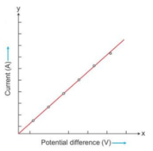
- The slope of the graph is the reciprocal of the resistance of the conductor.
Slope = ΔI/ ΔV = 1/(Resistance of conductor) - Conductance: It is defined as the reciprocal of resistance.
Conductance = 1/Resistance of conductor
Conductance = 1/Resistance - Hence, the slope of the I–V graph gives the conductance of the conductor.

Ohmic and Non-ohmic Resistors
- Ohmic resistors: The conductors which obey Ohm's law are called ohmic resistors or linear resistances.
For such resistors, a graph plotted for the potential difference V against the current I is a straight line, and the value of resistance R is the same irrespective of the value of V or I. - Non-ohmic resistors: The conductors which do not obey Ohm's law are called non-ohmic resistors or non-linear resistances.

- Superconductors: A superconductor is a substance of zero resistance (or infinite conductance) at a very low temperature.
The superconductors can be very useful provided it is possible to obtain them at room temperature. The size of computers could then be reduced to a few centimetres and power lines could then be made as thin as a single cable.
Specific Resistance or Resistivity
The resistance of a wire depends on the following factors:
- Directly proportional to the length (l) of the wire
- Inversely proportional to the area of cross-section of the wire
- Nature of the material of the wire
R ∝ l/A
R = ρ. l/πr2
- Here, ρ is the constant of proportionality and is called the electrical resistivity or specific resistance of the material of the wire.
- The resistivity will be given as
ρ = RA/l - Resistivity is the resistance of a wire of that material of unit length and unit area of cross-section.
- Its SI unit is ohm-metre (Ω m).
- Conductivity: The reciprocal of resistivity is called conductivity. It is represented by σ.
σ = 1/ρ = 1/RA - Its SI unit is ohm−1 metre−1 or siemen metre−1.
Choice of Material of Wire
The choice of material of a wire depends on the purpose for which the wire is to be used.
- The wires which are used for electrical connections and power transmission should possess negligible resistance.
- The resistance wires (or standard resistors) are made of materials such as nichrome, manganin, constantan etc., for which the resistivity is quite large and the effect of change in temperature on their resistance is negligible.
- A fuse wire is made from an alloy of lead and tin because its resistivity is high and melting point is low.
- A wire made of tungsten is used for the filament of an electric bulb because it has a high melting point and high resistivity.
- A nichrome wire is used as the heating element in appliances such as a heater, toaster and oven, because the resistivity of nichrome is very high and increase in its value with increase in temperature is also high.
Electromotive Force, Terminal Voltage and Internal Resistance of a Cell
- When no current is drawn from a cell, i.e. when the cell is in open circuit, the potential difference between the terminals of the cell is called its electromotive force (emf).
- The emf of a cell is denoted by the symbol ε (epsilon). Its unit is volt (V).
Factors Affecting the EMF of a Cell
- The emf of a cell is the characteristic of the cell. It is different for different kinds of cells.
- The emf of a cell depends on
・Material of the electrodes
・Electrolyte used in the cell - It is independent of
・Shape of electrodes
・Distance between the electrodes
・Amount of electrolyte - The emf of a cell is also defined as the energy spent (or work done) per unit charge in taking a positive charge around the complete circuit of the cell.
ε = W/q0
Terminal Voltage of a Cell
- When current is drawn from a cell, i.e. when the cell is in a closed circuit, the potential difference between the electrodes of the cell is called its terminal voltage.
- The terminal voltage of a cell is denoted by the letter V. It is also expressed in volt (V).
- The terminal voltage of a cell is defined as the work done per unit charge in carrying a positive charge around the circuit connected across the terminals of the cell.
V = W’/q0 - The terminal voltage V of a cell is less than its emf ε by the amount of energy spent in the flow of unit positive charge (taking q0 = 1 C) through the electrolyte inside the cell.
ε = V + v - When a larger current is drawn from the cell, a greater number of charge carriers flows through the electrolyte, and hence, more work is done. This results in more voltage drop v and hence less terminal voltage V.
Internal Resistance of a Cell
- When current is drawn from a cell, it flows from the anode to the cathode in the external circuit and from the cathode to the anode inside the cell through the electrolyte so as to maintain a continuous flow.
- The resistance offered by the electrolyte inside the cell to the flow of current is called the internal resistance of the cell. It is denoted by r. Its unit is ohm Ω.
- When current I is drawn from the cell of which the internal resistance is r, the voltage drop is v = Ir

Relationship between the emf, terminal voltage and internal resistance
r = v/l = ε – V/l = (ε – V)/(V/R) = (ε/V – 1)R
Factors affecting the internal resistance of a cell: The internal resistance of a cell depends on the following four factors:
- Surface area of the electrodes
- Distance between the electrodes
- Nature and concentration of the electrolyte
- Temperature of the electrolyte
Resistors in Series
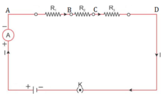
- The current in series remains the same across all the resistors.
- The resultant resistance of the circuit is given as
RS = R1 + R2 + R3 - Here, Rs is the resultant resistance. The resultant resistance is greater than all the resistances.
Resistors in Parallel

- The potential difference in parallel remains the same across all the resistors.
- The resultant resistance of the circuit is given as
1/RP = 1/R1 + 1/R2 + 1/R3 - Here, Rp is the resultant resistance. The resultant resistance is lesser than all the resistances.